One important component of lithium ion batteries is the separator, a thin, electronically insulating foil which physically separates the two electrodes. Usually the separator is made of polymeric material.
In order to measure the performances of separators, the MacMullin number was introduced as the ratio of the ionic conductivity of the pure electrolyte, and the ionic conductivity of the separator foil filled with electrolyte.
In this application note, the MacMullin number is calculated by applying the so-called stacking method. This method consists of performing electrochemical impedance spectroscopy on samples with different stack thickness, achieved by increasing the number of separators inside the cell. Then the ion resistance is calculated from the data fitting and is plotted versus the number of separators in the cell. The slope gives the MacMullin number.
One important component of lithium ion batteries is the separator foil – a thin, electronically insulating, porous membrane that prevents the electrodes from being in direct contact with each other while being permeable to ionic current. To maintain a good lithium ion battery performance, the resistance of a separator foil filled with electrolyte should be low. Consequently, information about the effective ion conductivity of these systems is an important parameter for the performance of a separator material.
Usually, the focus is not on the effective ionic conductivity, but on another quantity: the so-called MacMullin number NM [1]. The MacMullin number is the ratio of the ionic conductivity of the pure electrolyte σelectrolyte and ionic conductivity of the separator foil filled with electrolyte σseparator (Equation 1).
Therefore, the MacMullin number is a quantity that describes the decrease of the effective conductivity by the presence of a separator foil. For lithium ion battery separators, often a value between 4 and 20 is found [1–3]. Theoretically, the MacMullin number is linked to the separator foil’s porosity ε and tortuosity τ [2, 3].
Chemicals
As electrolyte, a 1 mol/L LiPF6 (lithium hexafluorophosphate) solution in a 1:1 ratio in volume mixture of EC (ethylene carbonate) and DMC (dimethyl carbonate, purchased from Sigma-Aldrich / Merck KGaA) was used without any further purification. After receiving, the electrolyte was stored and handled inside of an argon-filled glove box. As battery separator material, a tri-layer separator based on polyethylene/polypropylene with a thickness of 21.5 μm was used.
Sample preparation and measuring setup

Circular specimens with a diameter of 12 mm were punched out from the separator foil. To ensure an optimal wetting, the specimens were stored for at least 24 hours in the electrolyte solution.
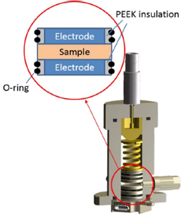
For the electrochemical measurements, a TSC battery standard cell (Figure 1) in combination with a Microcell HC setup was used.
As current collectors, two planar stainless steel disc electrodes (diameter 8 mm) press-fitted into a PEEK sleeve were used. The cell constant is the ratio of the electrode area A (cm2) and its thickness l (cm), and it is measured in cm-1. To calculate the cell constant, the area of the stainless steel electrodes and the separator thickness were measured, resulting in a cell constant value of 0.0043 cm-1.
The cell constant, together with the resistance related to the bulk ion transport inside of the porous separator network Rion (Ω), is used in the calculation of the conductivity σ (S cm-1, Equation 2).
The contact pressure applied onto the electrolytesoaked separator foil stack inside of the TSC battery cell was adjusted to approximately 100 kPa using a gold-plated spring with a spring constant of 2.43 N mm-1. At this contact pressure, no significant compression of the separator foil was found.
In the Microcell HC setup, the temperature is adjusted via a Peltier element, with an accessible temperature range of -40 °C to +100 °C. To accurately measure the temperature, a Pt100 temperature sensor is embedded in the base unit of the TSC battery cell, at a position very close to the sample. The accuracy of the temperature measurement is 0.1 °C with respect to the sensor position inside of the base unit. For the determination of the MacMullin number, the temperature was adjusted to 20.0 °C.
Because the TSC battery measuring cell is completely airtight, the experiments took place on the Microcell system outside of the glove box.
For the impedance measurements, a Metrohm Autolab PGSTAT204 equipped with a FRA32M module was used. The communication with the temperature controller is integrated in the NOVA software enabling automated measuring routines.
Measurement parameters
The impedance measurements were performed at a frequency range of 1 MHz to 100 Hz with an amplitude of 10 mV.
Impedance measurements were taken on samples with different stack thickness, achieved by increasing the number of separators inside the cell.
After reaching the temperature set point of 20.0 °C, a waiting time of 300 s was chosen to ensure for complete thermal equilibrium.
| Step | Action to be performed |
|---|---|
| 1 | Transferring the cell into the glove box and loading the cell with one specimen of the electrolyte-filled separator foil. |
| 2 | Taking the prepared cell out of the glove box and connecting it to the Microcell HC cell stand. |
| 3 | Connecting the measuring device (2-electrode configuration). |
| 4 | Setting the temperature to 20.0 °C and waiting for 300 s. |
| 5 | Performing an impedance spectroscopy measurement. |
| 6 | After finishing step 5, repeating steps 1–5 by adding further specimens of the electrolyte-filled separator foil (one per loop) until a stack of five specimens is created. |

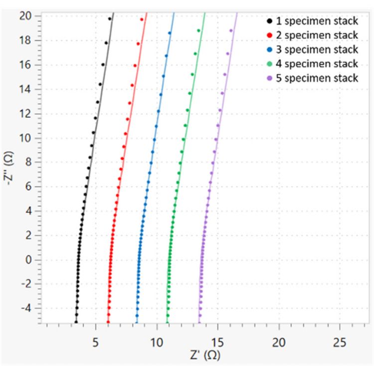
The resulting impedance spectra for different stack thicknesses are shown in Figure 2.
At high frequencies, the impedance behavior is dominated by inductive effects caused by the connection cables. The intersection at the Z’-axis is close to the bulk resistance value for bulk ion transport inside of the porous separator network. In absence of the inductive behavior at high frequencies, they would be identical. The increase at lower frequencies is then caused by electrode polarization.
As expected, increasing the stack thickness by adding further specimens of the electrolyte–soaked separator foil leads to a shift to higher values for the intersection point due to the higher bulk resistance value.

The spectra were fitted with the equivalent circuit shown in Figure 3.
The inductance Icable takes into account the high frequency contributions by the electrical cables and connectors, the resistor Rion represents the ion migration in the porous separator network, and the constant phase element CPEpol describes the electrode polarization at low frequencies.
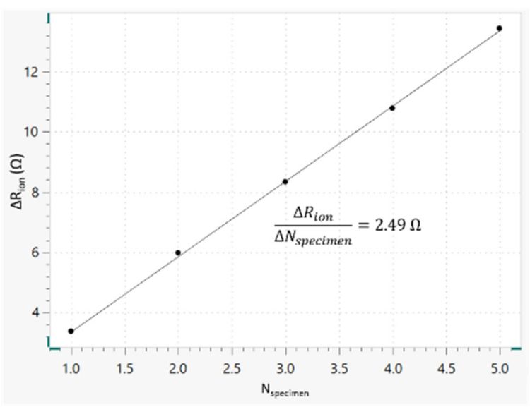
The resulting stack thickness-dependent values for Rion are given in Table 2. The fit error of Rion was lower than 0.4% in all cases.
| Nspecimen | Rion/Ω |
|---|---|
| 1 | 3.38 |
| 2 | 5.98 |
| 3 | 8.34 |
| 4 | 10.78 |
| 5 | 13.43 |

A plot of these values shows a linear relationship, where the slope gives a value of 2.49 Ω for the ionic resistance change per added specimen ΔRion / ΔNspecimen (Figure 4).
Taking into account the separator thickness d, the active area A of the stainless steel electrode, and the resistance per added specimen ΔRion / ΔNspecimen, the corresponding ionic conductivity of the electrolyte-soaked separator σseparator can be calculated as shown in Equation 3.
Here, a value of σseparator = 1.7 mS cm-1 was measured at 20 °C. The conductivity of the pure electrolyte solution at 20.0 °C was determined to be σelectrolyte = 9.9 mS cm-1.
Therefore, the MacMullin number was calculated to be NM = 5.8 which lies within the typical range for such separators [3].
It should be mentioned that Raccichini et al. found that the MacMullin number can be slightly dependent on the chosen electrolyte solution [4], although Landesfeind et al. showed that there was no dependence of the MacMullin number on the electrolyte salt, solvent composition, or salt concentration for the samples chosen by them [3]. Therefore, further research has to be performed to shed more light on the influence of the electrolyte properties on the determined MacMullin number values for separator foil. Ideally, the MacMullin number should be determined by using the electrolyte that is used for the final application.
In this application note, the so-called stacking method is applied to determine the MacMullin number of separator foils. A Metrohm Autolab Microcell HC setup combined with a TSC battery standard cell is used, together with a typical lithiumion battery electrolyte as well as a typical separator material.
The results presented here are part of a sub-project related to the project LiMES funded by the Federal Ministry for Economic Affairs and Energy as part of the 7. Energieforschungsprogramm which is highly appreciated.
- P. Arora, Z. Zhang, Chem. Rev. 2004, 104, 4419- 4462
- M. J. Martínez, S. Shimpalee, J. W. Van Zee, J. Electrochem. Soc. 2009, 156 (1), B80-B85.
- J. Landesfeind, J. Hattendorff, A. Ehrl, W. A. Wall, H. A. Gasteiger, J. Electrochem. Soc. 2016, 163 (7), A1373-A1387.
- R. Raccichini, L. Furness, J. W. Dibden, J. R. Owen, N. García-Araez, J. Electrochem. Soc. 2018, 165 (11), A2741-A2749.
 Share via email
 Download PDF